General

No, there is no minimum order quantity for our standard products while ordering from us.
** While we don’t have a minimum order quantity, our distributors may have it.   

Yes, we do offer sensor samples.

Fill out the request for a sample form to qualify for a free sample. Once we receive your request for a free sample Anfield Sensors’ specialist will contact you to learn more about your application, to suggest the most suitable product.

Click here to fill out the form to request a free sample.

Our trusted sensor distributors keep a stock of our standard products. We also offer expedited delivery service for some of the standard products.

Need help finding a distributor near you?

Give us a call to help find you the nearest distributor.

Toll Free (US & CANADA): 1-877-774-8808 or Tel: 905.303.8700

Yes, we offer private labelling services.

Yes, we have developed and continue to develop custom sensors for companies looking for a product that is not found in the market and for some of the largest motion and control companies in the world

Anfield Sensors Inc. offers a standard warranty of 1 year for all our sensors.

Yes, we do offer oxygen cleaning services for some of our products.

A sensor is a generic term for any device that converts an input (pressure, temperature, level) into an electrical signal. A switch and transducer are both sensors. A switch is a discrete device that will change the state of an electrical contact at a certain input value. A transducer is an analog device that will translate the input to an electrical output (either voltage or current).

A switch is generally more economical than a transducer. If you are looking to only know whether the system is above or below a state, then a switch provides that information at a much lower cost.

Pressure Switches

There are many different configurations for a switch and it can be confusing. At the minimum, to select a switch you will need the following items: set point value, overpressure value, process connection, switch configuration, electrical connection and electrical rating.

If you want us to select the switch please provide the following information:

  • Set Point Value (rising or falling)
  • Maximum System Pressure
  • Process Connection
  • Switch Configuration
  • Electrical Connection
  • Amperage/Voltage (Resistive/Inductive)

Most of the common process connections that we offer are shown on the switches catalogue page. If you are purchasing a large amount then it is possible to custom-make the process connections based upon your requirements.

Sometimes we offer more connections than what is shown in our documents. So it is best to ask. For larger orders, we can custom make any electrical connections per your requirements.

Click here to view the electrical configuration page

A blade contact switch is a mechanism that directly translates pressure to the distance between the contact bridge and the electrical terminals. Near the actuation and deactuation point, a blade contact switch may experience contact bounce or chatter, where there is rapidly pulsed electrical current instead of a clean transition from zero to full current.

A snap-action switch is a mechanism that avoids contact bounce by design. At certain pressures, the movable contact snaps to a position providing a cleaner electrical current transition and is a more reliable switch.

A blade contact switch is a more economical mechanism and should be used when price is the deciding factor.

If plugging into a PLC and you want to minimize the effects of contact bounce, a snap action microswitch can be used.

If the switch is to directly energize a relay or a valve, a 10 amp snap action microswitch is the best choice.

Most of our switches it is possible to only set the actuation set point or deactuation set point value.

Each switch has an over pressure rating defined in the specifications. This specification is based upon a static pressure test. The values are related to the wetted parts.

For dynamic applications, it is best to build in a safety factor by using 30 to 50 % lower over pressure for dynamic pressures.

A pressure snubber can be integrated into the switch that acts as a hydraulic damper. This reduces the amplitude of pressure spikes to the switch ensuring that the switch overpressure limit is not exceeded.

Pressure Transducers

The difference between pressure references is based upon the differences on what is the zero pressure reference.

Absolute pressure uses a perfect vacuum as the zero reference. The measurement is the sum of gauge pressure and atmospheric pressure.

Gauge pressure is a vented sensor that uses ambient air pressure as the zero reference. The gauge pressure measurement is positive for pressures above ambient air pressure and negative for pressures below ambient air pressure.

Sealed pressure seals ambient air pressure present at the factory as the zero references. The sealed pressure reference will be zero if exposed to the same ambient conditions.

Each electrical signal output has some advantages and disadvantages. Below is a brief description of the outputs and why they are used:

Digital Output – A digital output signal provides more information than an analog signal. These sensors are referred to as smart sensors as it can give more information. In I2C sensors (similar to TI2C), the sensor requires four wires (two power and two for communication), responds based upon a unique address and the sensor’s digital signal is less prone to noise.

4-20 mA Output – The 4-20 mA current loop sensing is the industry standard for process measurement. It uses 4 mA as the zero references and 20 mA as full scale and allows for a 0 mA to indicate a break in the current loop.

The current loop sensor operates by using a current regulator that turns supply voltage into current proportional to measurement. As long as there is enough supply voltage, the varying supply voltage does not impact the current output of the sensor.

It is popular due to its simplicity (2 wire installation), measurement insensitivity to supply voltage, insensitivity to the voltage drop caused by circuit length, and works with a large range of power supplies. The disadvantage is that care needs to be taken to avoid ground loops.

Ratiometric Output – A ratiometric sensor is quite popular in the automotive industry due to its low power consumption while still producing a high-level signal for 5 V. When operated with the nominal 5 VDC power supply, the offset voltage, or zero reference, is 0.5 V and full-scale output is 4.5 V.

The ratiometric output uses the same supply voltage for the sensor excitation and for the voltage reference for the measurement circuitry. Due to this trick, it reduces the voltage reference error and allows for a slightly higher accuracy sensor.

It has the added benefit of having lower power consumption than other voltage output devices. The drawback is the power supply needs to be a regulated 5.0 VDC power supply and the signal output is a voltage. All voltage signal outputs have a disadvantage due to voltage drop and noise sensitivity. As the measurement signal is voltage, its accuracy is directly affected by the voltage drop across the cable length from the sensor to the receiver. Ratiometric units are used when accuracy is optimized and noise and distance from the sensor can be minimized.

Voltage Output – Voltage outputs (0-5 V, 0-10 V, 1-5 V, 0.5-4.5 V, 1-6 V and 0.25-10.25 V) are similar to the ratiometric output but operate with different power supplies.

The voltage outputs have the same drawbacks as the ratiometric (voltage drop and noise sensitivity) as well as introducing more error due to having higher power input and more active components used to convert the supply voltage to the output voltage. Due to this these sensors generally have theoretically the lowest accuracy. The benefits of voltage sensors are the signal configuration allows for easy measurement, as it is cheaper to measure the voltage with the control system and signal receivers, and it can work well over small distances and low noise environments. Voltage output sensors consume less power than 4–20mA sensors.

Initially, the difference existed to differentiate between current and voltage output. A transmitter was a pressure sensor that outputted a current signal (4–20mA) and a transducer indicated a pressure sensor that had a voltage output signal (0–10VDC). Nowadays, the distinction is reduced and the terms are interchangeable.

Proof pressure is the maximum pressure that the sensing element can withstand without causing irreversible damage. Proof pressure is a static pressure measurement that needs to be reduced if dynamic pressures are present.

Burst pressure is the maximum pressure that the transducer can withstand before rupture. Pressures above this will cause complete failure of the transducer and may cause leakage.

Yes, the optional snubber can be installed into our pressure transducers to dampen the hydraulic signal. The snubber causes the amplitude of the pressure peaks to be reduced. Due to the dampening, the hydraulic pressure signal will have a lag from the true system pressure.

BFSL stands for the best fit straight line of the sensor output. A best fit straight line is a straight line that is fitted to the actual sensor output to minimize the difference between the actual sensor output and the line’s slope and offset.

The long term drift of a sensor is a measurement of how the sensor changes during operation. The test consists of keeping a pressure value of 90% and maintaining it for 30 days. Before and after the test, the lower range value and the span are measured to determine whether there is a drift in one direction or random drift.

Thermal error is the inaccuracy in the pressure measurement caused by a change in temperature. Conventional pressure sensors are somewhat sensitive to temperature variations. Temperature can impact the mechanical components that comprise the sensor or it can affect the electrical components.

Operating temperature is the range of temperatures that the sensor can operate without damage. The temperature range indicates the inclusive minimum and maximum temperatures the sensor can operate in.

Compensated temperature is the temperature range that the sensor is guaranteed to meet the thermal error specifications. This value is based upon quasi-static temperatures.

If large thermal transients occur within the compensated temperature range, it can cause errors out of bounds of the thermal error specification. This is because large thermal gradients exist in the sensor that can introduce significant inaccuracies to the pressure measurement.

Yes, it is possible. The standard pressure offerings are shown in our catalogue but it is possible to have any pressure range within the minimum and maximum pressure ranges.

The sensor response time can be separated from the sampling rate of the electronics and the response time of the mechanical part. The sensor sampling rate is fixed by the electronics and is indicated in the specifications. The response time of the mechanical part is a more complex function that depends upon the sensing element construction and range, the type of impulse and the amplitude.

Yes, shock and vibration can cause mechanical failure either of the sensor, electronics, or electrical connector or it can increase the inaccuracy of the transducer as the sensing element will convert the stress caused by vibration to strain.


Our transducers are tested to component failure. The exact vibration profile and mounting impact the sensor accuracy and are quite application dependent.

Temperature Switches

Bimetal creep action switches (S7TAF/S8TAF) consist of two strips of dissimilar metal that expand at different rates causing the bimetal strip to bend into an arc. Their name is derived from their slow break or make movement. Due to their movement, they offer a low temperature differential but the strip may have a shorter life due to contact arcing.

Bimetal snap action switches (S2TAF/S3TAF/S5TAF/S6TAF) are defined by their movement. The bimetal strip is shaped so that it offers an instantaneous and reliable switching operation as the bimetal strip moves between two stable positions, causing an audible snap. The rapid contact separation allows for a long contact life and fast switching time but it comes with an increased differential.

The optimal probe length is one that maximizes the insertion length in the media. Overall the longer the probe, the better the heat transfer and the response time of the sensor. If there is space limitations and insertion limitations then we also offer sensors that have no probe (S2TAF)

No, our temperature switches come factory set.

Temperature Transducers

The type of applications depend upon whether the user does not require high accuracy and just wants to know whether the temperature is increasing or decreasing, or a temperature measurement that requires accuracy.

If you are looking for rough temperature measurement, the solid-state sensor is an economical choice.

If you have an accuracy requirement, the PT1000 measuring element is more accurate and faster than the solid-state.

A solid-state measuring element is a silicon IC that has a positive temperature coefficient (PTC), or as temperature increase the resistance increases. It is quite linear and inexpensive but has a large time constant and a smaller temperature range.

A PT1000 measuring element is made of platinum (PT) and has a resistance value of 1000 Ω at 0°C. The sensor is generally considered to be quite stable, accurate, and has a high-temperature range but is more expensive.

Ambient temperature range is the range of temperatures that the electronics can withstand and still operate.

Level Switches

All our float level switches (LF1/LF2) are to be mounted vertically. The visual level indicator(VE/VEC) is to be mounted on the side of the tank.

To adjust the level you need to cut the length of the rod to suit the setpoint level that you need. Remove the float of the LF1/LF2 and cut the rod to length. In the catalogue, there is a chart that indicates the exact length that is needed for your set point level.

Click here to Download Level Switch Chart

Fluid sloshing can cause the level switch to turn on and off frequently as the rod elastically deforms. Using a reinforced rod reduces the effect of fluid sloshing as the rod sway is reduced.

This will not stop the float from bobbing with the fluid sloshing. If you are looking for a level switch that is insensitive to fluid sloshing, the ULS has compensation built into the program to limit the effects of fluid sloshing.

Yes, you can just flip the visual sight level gauge to change the alarm.

Ultrasonic Level Sensors

The ultrasonic level sensor operates using a time-of-flight measurement system. The ultrasonic sensor makes a high frequency sound wave, similar to a loudspeaker, causing a sound wave to travel through the medium and listens for the echo. Using the time it takes between the pulse and the echo, it calculates the distance the pulse travelled by estimating the speed of sound. The level measurement that is displayed is half the distance that the sound wave travelled.

Yes, ultrasonic level sensors work well outside if it stays within the temperature limits and is properly installed. The sensor uses a temperature measurement to calculate the distance the pulse travelled. This accuracy of the temperature measurement is proportional to the accuracy of the sensor and the following needs to be controlled:

If the surface of the target surface is higher temperature than the air, it will cause errors in measurement as there is a temperature gradient that the ultrasonic pulse has to travel through. Care should be taken to avoid this problem.

If there is direct sunlight on the sensor, the sensor temperature measurement will be inaccurate and the level measurement will be inaccurate. It is best to block the sensor from direct sunlight using a sheet metal covering.

If you save the settings to the non-volatile memory, the settings will remain after powering off the sensor.

A thorough programming manual will be available online in the ultrasonic level sensor webpage.

Electrical

An IP, or ingress protection, rating is defined by IEC 60529:1989. It defines the level of protection that the enclosure offers against solid foreign objects (tools, dirt, and dust) and water for electrical objects. It applies to the enclosure around the sensor and its protection.

There are two numerals that define the IP rating: the first numeral defines protection against hazardous parts and solid foreign objects and the second numeral defines protection against water. The exact degree of protection is as follows:

Table 1: Degrees of protection against access to hazardous parts indicated by the first characteristic numeral

First Characteristic Numeral

Brief Description

Description

0

Not protected

–

1

Protected against access to hazardous parts with the back of a hand

The Access probe, sphere of ∅50 mm shall have adequate clearance from hazardous parts.

2

Protected against access to hazardous parts with a finger

The jointed test finger of ∅12 mm, 80 mm length, shall have adequate clearance from hazardous parts

3

Protected against access to hazardous parts with a tool

The access probe of ∅2.5 mm shall not penetrate.

4

Protected against access to hazardous parts with a tool

The access probe of ∅1.0 mm shall not penetrate.

5

Protected against access to hazardous parts with a tool

The access probe of ∅1.0 mm shall not penetrate.

6

Protected against access to hazardous parts with a tool

The access probe of ∅1.0 mm shall not penetrate.

NOTE: In the case of the first characteristic numerals 3, 4, 5, and 6, protection against access to hazardous parts is satisfied if adequate clearance is kept.


Table 2: Degrees of protection against solid foreign objects indicated by the first characteristic numeral

First Characteristic Numeral

Brief Description

Description

0

Not protected

–

1

Protected against solid foreign objects of ∅50 mm  and greater

The object probe, sphere of ∅50 mm shall not fully penetrate 1)

2

Protected against solid foreign objects of ∅12,5 mm  and greater

The object probe, sphere of ∅12,5 mm shall not fully penetrate 1)

3

Protected against solid foreign objects of ∅2,5 mm and greater

The object probe, sphere of ∅2,5 mm shall not penetrate at all 1)

4

Protected against solid foreign objects of ∅1,0 mm and greater

The object probe of ∅1,0 mm shall not penetrate at all 1)

5

Dust-protected

Ingress of dust is not totally prevented, but dust shall not penetrate in a quantity to interfere with satisfactory operation of the apparatus or to impair safety

6

Dust-tight

No ingress of dust

1) The full diameter of the probe shall not pass through an opening of the enclosure


Table 3: Degrees of protection against water indicated by the second characteristic numeral

Second Characteristic Numeral

Brief Description

Description

0

Not protected

–

1

Protected against vertically falling water drops

Vertically falling drops shall have no harmful effects

2

Protected against vertically falling water drops when enclosure tilted up to 15°

Vertically falling drops shall have no harmful effects when the enclosure is tilted at any angle up to 15° on either side of the vertical

3

Protected against spraying water

Water sprayed at an angle up to 60° on either side of the vertical shall have no harmful effects

4

Protected against splashing water

Water splashed against the enclosure from any direction shall have no harmful effects

5

Protected against water jets

Water projected in jets against the enclosure from any direction shall have no harmful effects

6

Protected against powerful water jets

Water projected in powerful jets against the enclosure from any direction shall have no harmful effects

7

Protected against the effects of temporary immersion in water

Ingress of water in quantities causing harmful effects shall not be possible when the enclosure is temporarily immersed in water under standardized conditions of pressure and time

8

Protected against the effects of continuous immersion in water

Ingress of water in quantities causing harmful effects shall not be possible when the enclosure is continuously immersed in water under conditions which shall be agreed between manufacturer and user but which are more severe than for numeral 7

9

Protected against high pressure and temperature water jets

Water projected at high pressure and high temperature against the enclosure from any direction shall not have harmful effects

The author thanks the International Electrotechnical Commission (IEC) for permission to reproduce Information from its International Standards. All such extracts are copyright of IEC, Geneva, Switzerland. All rights reserved. Further information on the IEC is available from www.iec.ch. IEC has no responsibility for the placement and context in which the extracts and contents are reproduced by the author, nor is IEC in any way responsible for the other content or accuracy therein.

Copyright © 2013 IEC Geneva, Switzerland. www.iec.ch

No, we generally do not test our products to NEMA enclosure protection ratings. The following shows a conversion from NEMA 250-2003 enclosure type ratings to IEC 60529 enclosure type ratings.

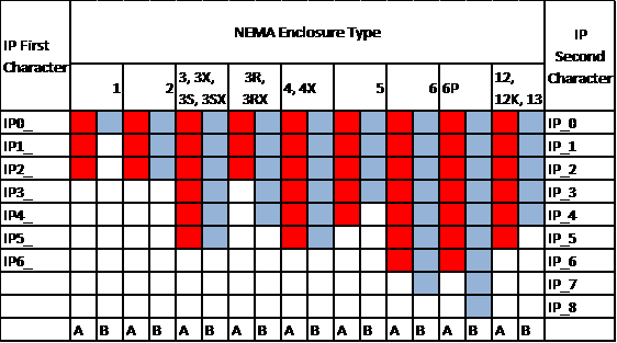
The exact conversion of NEMA ratings works only in one direction from NEMA to IP ratings. NEMA ratings requires an outdoor corrosion test, a gasket aging test, a dust test, an external icing test, and no water penetration in the water test. Therefore, this chart only gives a rough idea of conversions and should not be used to state that an IP rated product can replace a NEMA rated component.

Our switch only indicates the resistive load in the specifications. Inductive loads are generally found with our 10 amp micro-switch and the exact amperage limit can be found in parentheses.

This Site Uses Cookies

We are using cookies on our site. These cookies enhance your experience, and improve the quality of our site.

We have successfully received your form!

Thank you for the information. One of our representatives will get in touch with you shortly.